UK / Europe: +44 1268 568200 USA / Canada: +1 877 215 8463
in
0%

EMI Filter Modules are quiet guardians inside modern electronic equipment. They reduce unwanted electromagnetic noise before it travels through power lines, signal cables, or a metal enclosure. A switching power supply may create sharp current pulses every few microseconds. Without control, those pulses can disturb a nearby sensor, radio receiver, or medical instrument. The filter acts like a selective gate. It allows useful power to pass while weakening disruptive frequencies.

Henry W. Ott, a respected EMC engineer and author, described the broader objective clearly: “The goal of EMC is to ensure that different pieces of electronic equipment can operate in close proximity to each other without interfering with each other.” His statement explains why EMI Filter Modules matter beyond simple noise reduction. They support reliable operation across industrial controls, automotive systems, consumer devices, and communications equipment. Their internal capacitors, inductors, common-mode chokes, and shielding elements work together. Placement matters. Grounding matters even more.

Real installations are rarely perfect. A filter that performs well in a laboratory may behave differently beside a long cable or a poorly bonded enclosure. That uncomfortable detail deserves attention. Design teams must examine impedance, frequency range, load current, heat, and safety requirements. They should also test the complete system, not only the module. This article explores what EMI Filter Modules contain, how they suppress interference, and why practical installation decisions can determine their final performance.
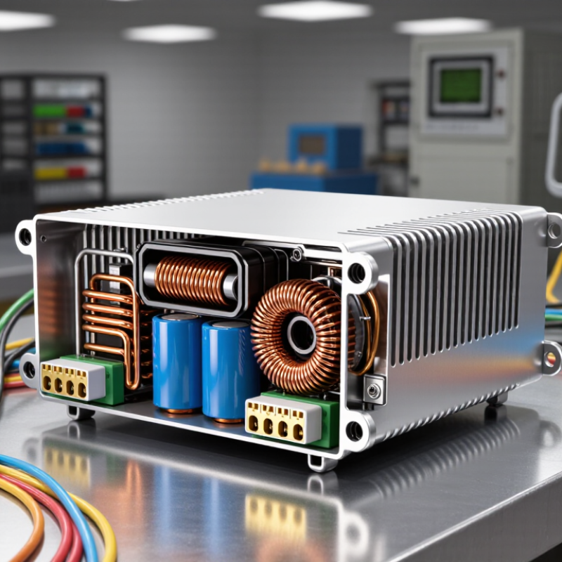
What Are EMI Filter Modules and How Do They Work?

What Is an EMI Filter Module?

An EMI filter module is a compact electrical assembly that reduces unwanted electromagnetic interference. It usually contains capacitors, inductors, resistors, or ferrite components. These parts control high-frequency noise without stopping the equipment’s normal power flow. In practical equipment, the module often sits between a power source and sensitive circuits.

The operating principle is selective filtering. Inductors resist rapid changes in current, while capacitors provide a path for high-frequency noise to ground or return lines. This action helps prevent interference from entering or leaving a device.

A well-designed module can reduce radio-frequency noise, protect signal quality, and support more stable operation. It may also limit disturbances created by switching power supplies, motors, or digital processors.

The physical design matters as much as the schematic. Short connections, correct grounding, and suitable voltage ratings strongly affect performance. During testing, engineers often check both conducted emissions and the equipment’s operating behavior. A filter that works well in a laboratory may perform poorly after installation. Cable length, enclosure structure, and nearby circuits can change the result.

This is an easy detail to underestimate. I would not treat an EMI filter module as a universal cure. Its impedance, current rating, attenuation range, and installation position must match the actual noise problem. Even then, measurements may reveal unexpected interference paths.

Which Components Make Up an EMI Filter Module?

An EMI filter module combines several passive parts in a compact enclosure. The common-mode choke is usually the central component. Its paired windings suppress noise traveling together on power lines, while allowing normal current to pass. X capacitors connect across line and neutral. They reduce differential-mode noise between conductors. Y capacitors connect each line to protective ground, diverting common-mode noise safely.

Ferrite beads may handle high-frequency spikes near connectors. A discharge resistor helps drain stored energy from X capacitors after power removal. Some modules also include inductors, thermal fuses, shielding covers, and defined grounding points. Every part has a trade-off. A larger choke can improve attenuation, but it may increase resistance, heat, and size. That detail is easy to miss.

MarketsandMarkets reported that the global EMI shielding market could grow from about 7.1 billion dollars in 2023 to 9.9 billion dollars by 2028. This growth reflects rising noise-control demands in connected equipment. Meanwhile, IEC 61000-4-6 testing evaluates conducted disturbances from 150 kHz to 80 MHz. The module must therefore match the interference spectrum, not merely use more capacitance. In practical testing, poor grounding can defeat a carefully selected filter. One uncomfortable lesson remains: component ratings on paper do not guarantee system-level performance. Layout matters. Installation matters more.

What Are EMI Filter Modules and How Do They Work?

EMI filter modules reduce conducted electromagnetic interference by presenting high impedance to unwanted high-frequency noise while allowing the intended power signal to pass.

Typical components: A common-mode choke uses inductance to oppose common-mode noise, an X capacitor connects across the line and neutral conductors, Y capacitors connect each line to protective earth, and a resistor may discharge the X capacitor after power is removed.

The chart shows calculated reactance from standard component values using XL = 2πfL and XC = 1/(2πfC). Higher reactance generally means greater opposition to high-frequency noise.

How Does an EMI Filter Module Suppress Interference?

What Are EMI Filter Modules and How Do They Work?

An EMI filter module reduces unwanted electromagnetic energy entering or leaving electronic equipment. It usually combines inductors, capacitors, and sometimes damping components inside one compact housing. These parts create a high-impedance path for high-frequency noise while allowing the intended power signal to continue.

How Does an EMI Filter Module Suppress Interference?

The suppression method depends on the noise type. Common-mode chokes resist noise traveling in the same direction on multiple conductors. Differential-mode inductors oppose noise moving between power lines. Capacitors then divert high-frequency energy toward a suitable return path, often chassis ground.

In bench testing, a filter can noticeably reduce buzzing, unstable sensor readings, and interference on communication lines. Its performance depends on frequency, load current, impedance, and installation quality. A theoretically excellent filter may perform poorly when connected with long wires. That detail is easy to overlook.

Tips:

Install the module close to the interference source or equipment entry point. Keep noisy and clean wiring physically separated. Use short, wide connections for grounding. Check the rated voltage, current, temperature, and leakage limits before installation. Measure both before and after filtering with suitable test equipment. A filter that works at one frequency may be ineffective elsewhere. Ferrite material, cable layout, and enclosure bonding can also change the result. Results are rarely perfect. Careful testing remains essential.

Where Are EMI Filter Modules Used?

EMI filter modules are used wherever electronic equipment must control unwanted electromagnetic noise. They commonly sit at a power inlet, between a converter and its load, or beside a motor drive. Inside, common-mode chokes and capacitors suppress noise on power lines. The goal is simple: protect nearby circuits and help equipment meet electromagnetic compatibility requirements.

Their applications are broad. In electric vehicles, filters protect battery chargers, inverters, and high-voltage auxiliary systems. The International Energy Agency’s Global EV Outlook 2024 reported nearly 14 million electric car sales in 2023. That growth increases the need for reliable filtering around fast-switching power electronics.

Solar inverters, wind converters, industrial robots, elevators, and factory control cabinets also use these modules. A filter may be mounted inside a metal cabinet, close to a noisy relay, or beside a motor cable.

Data centers are another important setting. The IEA’s Electricity 2024 report estimated that data centers consumed about 460 TWh globally in 2022. Their electricity demand could exceed 1,000 TWh by 2026. Filters help reduce interference from dense server power supplies and cooling equipment.

Medical imaging systems and laboratory instruments use them for similar reasons. Small leakage currents still matter. A practical warning is often missed: a filter cannot repair poor grounding, excessive cable length, or incorrect installation. Engineers should test the complete system, not only the module. Real measurements can contradict an attractive datasheet.

How to Select the Right EMI Filter Module?

Selecting the right EMI filter module starts with the equipment’s electrical conditions. Check the maximum voltage, continuous current, surge level, and operating temperature. A filter rated too closely to the circuit may overheat or age quickly. Leave practical safety margin.

Identify the noise before choosing a filter. Common-mode noise travels along conductors together, while differential-mode noise moves between them. Use an oscilloscope, spectrum analyzer, or controlled bench test to locate the problem. Compare the measured noise frequency with the filter’s insertion-loss data. High attenuation at the wrong frequency provides little value. Look closely at impedance, connector layout, and cable length. Small details matter.

Installation can change performance significantly. Keep noisy and clean wiring separated, and make the grounding path short and wide. Select a module with suitable leakage current, insulation, environmental protection, and verified safety documentation. For motors, converters, and switching power supplies, consider vibration, heat, and repeated current peaks. Do not judge a filter by its size alone. Bigger is not automatically better. A common mistake is choosing the first filter that fits the enclosure. I have seen this approach pass a bench test but fail after cable routing changed. Test the complete assembly under realistic load, because the filter and system work as one. No selection is perfect. Recheck it.

What Are EMI Filter Modules and How Do They Work? - How to Select the Right EMI Filter Module?

Selection Dimension Common Options or Range How the Module Works When to Choose It Important Verification Points
Primary EMI Problem Conducted differential-mode noise, common-mode noise, or both Passive components attenuate unwanted high-frequency energy before it enters or leaves the equipment. Identify the dominant noise path through testing, probes, current clamps, or a spectrum analyzer. A filter designed mainly for common-mode noise may not adequately suppress differential-mode noise, and vice versa.
Filter Topology LC, π-type, T-type, common-mode choke, feedthrough, or combined network Capacitors shunt high-frequency noise, while inductors and chokes present impedance to unwanted current. Use combined or multi-stage topologies when noise spans a broad frequency range. Check possible resonance with the power source, converter, cable inductance, or downstream input capacitance.
Operating Voltage Low-voltage DC, automotive DC, industrial DC, single-phase AC, or three-phase AC The insulation system and capacitor ratings determine the maximum safe continuous voltage. Select a voltage rating above the highest normal operating voltage, including allowable tolerances and transients. Confirm working voltage, isolation voltage, impulse withstand, creepage, clearance, and capacitor safety classification where applicable.
Rated Current From signal-level current to several amperes or higher power-system ratings The inductor, terminals, conductors, and thermal design carry the load current while limiting noise current. Choose a rating exceeding the maximum continuous load current and account for startup or surge current. Review temperature derating, allowable voltage drop, RMS current, peak current, and heating under enclosure conditions.
Frequency Range Power filters commonly address noise from switching frequencies into the MHz range; signal filters may target higher bands. Attenuation varies with component values, parasitic effects, source impedance, load impedance, and layout. Match the filter’s effective attenuation band to the measured fundamental switching frequency and harmonics. Do not select by cutoff frequency alone; verify insertion-loss curves under conditions close to the actual circuit.
Insertion Loss Often specified in decibels across a stated frequency range; practical values vary by design and test setup. Insertion loss expresses the reduction of transmitted unwanted energy, usually measured in dB. Choose adequate attenuation with margin rather than relying on the maximum value at one frequency. Check whether the published curve is measured in a 50-ohm system or another source/load impedance arrangement.
Common-Mode Rejection Common-mode chokes and feedthrough structures are commonly used for shared noise on multiple conductors. Equal and opposite load currents largely cancel the magnetic flux, while common-mode currents encounter high impedance. Use for cable radiation, ground-referenced noise, and noise coupled onto all conductors in the same direction. Check saturation behavior, leakage inductance, winding balance, and the effect of cable placement and shielding.
Differential-Mode Attenuation Differential capacitors, series inductors, ferrite elements, or LC sections Suppresses noise voltage or current that appears between power or signal conductors. Use when switching current loops or converter ripple creates noise between the positive and negative lines. Evaluate ripple-current capability, capacitor heating, transient response, and any impact on control-loop stability.
Leakage Current Especially relevant to AC filters using capacitors connected from line or neutral to protective earth. Safety capacitors provide a path for high-frequency common-mode noise, which can create measurable earth leakage. Select low-leakage designs for portable, medical, battery-powered, or residual-current-protected equipment. Confirm normal leakage, touch current, discharge behavior, and compliance requirements for the final equipment.
Safety and Compliance Applicable electrical safety, EMC, environmental, and sector-specific requirements Certified insulation components and construction methods reduce shock, fire, and electromagnetic-interference risks. Choose components with documentation suitable for the target market and end-product certification process. Verify applicable capacitor class, dielectric strength, flammability rating, creepage, clearance, and recognized safety approvals.
Temperature Range Commercial, industrial, automotive, or other application-specific temperature classes Electrical characteristics, losses, insulation performance, and mechanical reliability change with temperature. Select a range covering ambient temperature, self-heating, airflow, and installation location. Apply current derating and verify component life at the highest expected internal temperature.
Package and Mounting PCB module, chassis mount, DIN-rail mount, panel mount, cable-mounted, or feedthrough The enclosure and mounting structure help control parasitic coupling and provide a defined current path. Choose a package that keeps unfiltered and filtered conductors physically separated. Check dimensions, terminal spacing, mounting torque, grounding method, vibration resistance, and access for servicing.
Installation and Layout Short connections, direct chassis bonding, shield termination, and separated input/output routing Minimizes parasitic inductance and prevents high-frequency noise from bypassing the filter. Use the shortest practical connections and place the module close to the cable entry or noise source. A correctly rated filter can perform poorly if input and output wiring run together or if the enclosure bond is inadequate.
Validation Method Bench testing, conducted-emissions measurement, radiated-emissions testing, and immunity testing Confirms that the complete equipment, filter, wiring, enclosure, and load operate together as intended. Test the final hardware in its intended mechanical configuration before compliance submission. Measure under normal load, worst-case switching conditions, startup, shutdown, and relevant cable configurations.

Note: Electrical ratings, insertion loss, leakage current, temperature limits, and compliance status are application-specific. Always use the latest technical documentation and validate the selected module in the complete end product.

FAQS

What is an EMI filter module?

It is a compact assembly that reduces unwanted electromagnetic noise. It usually sits between a power source and sensitive circuits. Normal power still passes through.

How does an EMI filter module work?

Inductors resist rapid current changes. Capacitors redirect high-frequency noise toward ground or return lines. The filter targets selected noise frequencies. It is not magic.

Which components are commonly included?

Common parts include chokes, capacitors, resistors, ferrite beads, and inductors. Some modules also contain thermal fuses, shielding covers, and grounding points. A discharge resistor can remove stored capacitor energy after shutdown.

What are X and Y capacitors used for?

X capacitors connect across line and neutral conductors. They reduce differential-mode noise between those conductors. Y capacitors connect lines to protective ground. Their leakage current requires careful control.

Where are EMI filter modules installed?

They may be installed at a power inlet or near a motor drive. Other locations include converter outputs, metal cabinets, and connector areas. Short connections usually improve performance. Placement matters greatly.

What equipment commonly uses EMI filter modules?

Electric vehicles, solar converters, industrial robots, elevators, and factory controls use them. Data centers also need filtering around servers and cooling systems. Medical instruments and laboratory equipment may require cleaner electrical conditions.

Can an EMI filter solve every interference problem?

No. It cannot repair poor grounding, long cables, or incorrect installation. Nearby circuits and enclosure design can create unexpected noise paths. I would not trust a datasheet alone.

How should an EMI filter module be selected and tested?

Match its voltage, current, impedance, and attenuation range to the actual noise. Check the interference frequency before choosing more capacitance. Test conducted noise and normal equipment operation together. Laboratory results may change after installation.

Conclusion

EMI Filter Modules are compact electrical assemblies designed to reduce electromagnetic interference that can disrupt signals, affect equipment performance, or cause unwanted noise in power and communication systems. They typically combine components such as capacitors, inductors, resistors, common-mode chokes, and shielding structures. Working together, these elements attenuate high-frequency noise while allowing the intended power or signal to pass through with minimal loss. Different filter designs target common-mode interference, differential-mode interference, or both, depending on the application.

EMI Filter Modules are widely used in industrial controls, power supplies, telecommunications equipment, medical devices, transportation systems, consumer electronics, and renewable energy equipment. Selecting the right module requires evaluating the operating voltage, current rating, frequency range, insertion loss, impedance, environmental conditions, mounting method, and available space. Designers should also consider safety requirements, grounding arrangements, thermal performance, and compatibility with the surrounding circuit to achieve reliable interference suppression.


Oliver

Oliver

Oliver is a dedicated marketing professional with extensive experience in developing clear, engaging, and results-focused content for modern businesses. As a key member of our marketing team, he has developed a deep understanding of the company’s products, services, and customer needs. His......