UK / Europe: +44 1268 568200 USA / Canada: +1 877 215 8463
in
Powerstax High Voltage Isolation Engineering

High Voltage Isolation Components & Advanced Galvanic Systems

Precision-engineered High Voltage Isolation Components rated up to 200 kV. Delivering partial-discharge-free insulation barriers, pulse transformers, ceramic bushings, and opto-isolated interfaces for green hydrogen electrolysers, medical imaging, defense, and wide-bandgap converter systems.

200kVMax Isolation Threshold
<5 pCPartial Discharge Rating
ISO 9001Certified Production
30+ YrsPower Engineering
Engineering Authority & Reliability

The Science of High Voltage Isolation Components

In modern high-power electrical engineering, high voltage isolation components form the critical boundary between high-potential energy domains and sensitive digital control architecture. As operating voltages escalate in green hydrogen megawatt electrolysers, silicon carbide (SiC) traction drives, medical linear accelerators, and defense pulse systems, ensuring failure-proof dielectric separation, low partial discharge, and extended creepage distance is no longer optional—it is mission-critical.

30+ Years of Magnetics & HV Mastery

Since 1992, Powerstax has designed, potted, encapsulated, and validated ultra-reliable isolation hardware in the UK and USA. Our historical field data covers millions of continuous operating hours without dielectric breakdown.

In-House Partial Discharge Testing

Every Powerstax high voltage component undergoes rigorous Partial Discharge (PD) testing using Faraday-shielded test chambers, certifying extinction thresholds well below 5 to 10 pico-Coulombs (pC) at 1.5x working voltage.

ISO 9001 & Traceable Materials

Full lot-traceability for medical grade silicones, vacuum-impregnated epoxy resins, high-alumina ceramics, and UL 94 V-0 flame-retardant polymers ensures complete compliance with global safety standards.

Custom Value-Added Engineering

Where off-the-shelf components fail under high dv/dt switching transients or extreme thermal cycling, our value-added solutions team custom-engineers geometries, creepage paths, and internal shielding.

Component Selection Guide

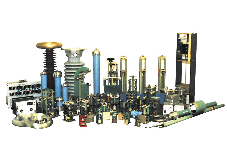
Recommended High Voltage Isolation Components

Explore our engineering-approved product lines designed to mitigate dielectric breakdown, surface tracking, and common-mode transient interference across demanding high-potential topologies.

HV Encapsulated Pulse Transformers

High Voltage Encapsulated Pulse Transformer

Reinforced isolation up to 50kV DC. Ideal for high dv/dt gate driving, radar modulators, and spark gap triggers with intra-winding capacitance < 15 pF.

HV Opto-Isolated Gate Drivers & Sensors

High Voltage Optocoupler Isolation Assembly

Fiber-optic and optical isolation assemblies rated to 100kV peak isolation, eliminating ground loops in SiC/GaN high-side inverter controls.

Ceramic & Cast Epoxy Bushings

High Voltage Ceramic Feedthrough Bushing

High-alumina ceramic and cycloaliphatic epoxy feedthrough bushings certified for 20kV to 200kV operation in SF6-free gas and transformer oil tanks.

Polymeric Dielectric Insulation Barriers

Custom High Voltage Dielectric Barrier Sheet

Precision-machined Kapton, Nomex, and silicone-mica composite insulation sheets with Comparative Tracking Index (CTI) > 600V (Group I).

Technical Specifications Matrix: Isolation Component Architecture

Isolation Component Type Operating Isolation Voltage Dielectric Strength Partial Discharge (PD) Inter-electrode Capacitance Primary Application Domain
Vacuum Epoxy Pulse Transformers 10 kV to 60 kV DC / Peak > 25 kV/mm < 5 pC @ 1.5x Un < 12 pF Pulsed power, Laser modulators, Radar systems
Opto-Coupled Feedback Arrays 15 kV to 100 kV Isolation > 35 kV/mm Non-measurable (< 2 pC) < 1 pF HV Switch-mode feedback, Medical X-ray control
High Alumina Ceramic Bushings 30 kV to 200 kV Continuous > 18 kV/mm Zero discharge @ working V N/A (Feedthrough) Hydrogen electrolysers, HV oil tanks, Subsea power
Silicone Elastomer Isolation Modules 5 kV to 45 kV Peak > 22 kV/mm < 10 pC @ 1.25x Un < 20 pF MIL-Spec COTS systems, Harsh environment power
Engineering Deep-Dive

Physics of Dielectric Insulation, Creepage, and Partial Discharge

Designing high-reliability high voltage isolation components requires balancing electrical field distribution, material dielectric constants, and environmental pollution degrees. Below is an engineering overview of the parameters that dictate component longevity under continuous high voltage stress.

1. Creepage & Clearance Distance Optimization

The distinction between clearance (the shortest distance through air) and creepage (the shortest distance along the insulating surface) is foundational to high voltage component design. As governed by IEC 60664-1 and IEC 61010-1 standards, high voltage isolation components must account for:

  • Pollution Degree 2 & 3 Environment: Conductive dust, moisture condensation, and chemical vapors alter surface resistivity, demanding corrugated or ribbed insulator profiles to extend tracking paths.
  • Comparative Tracking Index (CTI): Utilizing Material Group I polymers (CTI > 600V) drastically reduces surface carbonization risks when subject to persistent voltage gradients.
  • High Altitude Derating: Air density drops at elevated altitudes (e.g., aerospace applications), reducing air breakdown voltage according to Paschen's Law and requiring expanded physical clearance dimensions.

2. Elimination of Partial Discharge (PD)

Partial discharge is an electrical breakdown of a small region of a solid or liquid electrical insulation system under high voltage stress, which does not bridge the space between conductors. Over time, micro-voids within vacuum-cast epoxy or potted transformers erode dielectric material through localized electron bombardment, leading to catastrophic avalanche breakdown.

  • Vacuum Impregnation (VPI): Powerstax utilizes multi-stage degasification vacuum-pressure impregnation to extract microscopic air bubbles down to < 0.1 mbar before curing.
  • Electric Field Gradient Control: Faraday shields, rounded conductive field rings, and stress-cone geometries redistribute high field concentrations away from sharp metallic edges.
  • PD Inception (PDIV) & Extinction (PDEV) Voltages: Designing components where PDEV is 150% higher than peak working voltage guarantees partial discharge self-extinguishes during transient line surges.

Need Custom High Voltage Isolation Engineering?

Whether you require a modified creepage profile for high-altitude aerospace or a custom 150kV pulse isolation transformer for research laboratories, Powerstax engineers are available to review your field plots and thermal boundaries.

Get a Quote
Technology Trends

Future Technological Trends in High Voltage Isolation

The rapid transition toward renewable energy, high-frequency wide-bandgap semiconductors, and electrifying subsea industrial infrastructure is driving unprecedented evolution in high voltage isolation component designs.

1. High dv/dt Transient Immunity in Wide-Bandgap (SiC/GaN) Systems

Next-generation Silicon Carbide (SiC) and Gallium Nitride (GaN) power converters operate at switching speeds exceeding 100 kV/µs. Isolation transformers and optocouplers must feature ultra-low parasitic capacitance (< 2 pF) to prevent common-mode noise currents from corrupting low-voltage microcontrollers.

2. Phase-Out of SF6 in Favor of Bio-Based Resins

Environmental regulations restricting Sulfur Hexafluoride (SF6) gas are pushing procurement teams toward solid-state encapsulation and fluoronox gas blends. Powerstax leads this transition by developing high-thermal-conductivity eco-epoxies that eliminate greenhouse gases while enhancing heat dissipation.

3. Smart Embedded Fiber-Optic Partial Discharge Sensors

Industry 4.0 demands real-time structural health monitoring. Modern high voltage isolation barriers are increasingly embedded with integrated optical strain and partial-discharge sensing fibers, allowing predictive maintenance algorithms to alert operators before dielectric breakdown occurs.

4. Ultra-Compact Multi-Layer Molded Assemblies

As power densities exceed 50 W/in³, custom isolation components utilize multi-material co-molding (combining rigid ceramic cores with flexible silicone boots) to shrink physical footprints by up to 40% without sacrificing voltage withstand capacity.

Strategic Sourcing

Global Procurement Trends for High Voltage Isolation Hardware

B2B procurement executives facing volatile supply chains, stringent ESG mandates, and tightening technical specifications are shifting their sourcing methodologies for high-potential electrical hardware.

Trend 01: Vertical Integration

Turnkey Sub-Assemblies

Procurement teams are moving away from buying discrete isolated magnetic cores and potting compounds separately. Sourcing fully potted, factory-tested isolation modules reduces assembly labor and warranty liabilities.

Trend 02: Geopolitical Risk Reduction

Dual-Region Manufacturing

Establishing supply chains backed by engineering centers in both the UK and North America ensures continuity against regional transport bottlenecks, tariffs, and localized regulatory disruptions.

Trend 03: Total Cost of Ownership

TCO Over Initial Component Cost

Evaluating total failure cost (e.g., offshore electrolyser downtime or medical imaging field service calls) proves that spending 15% more on zero-PD rated isolation components yields a 10x ROI over equipment lifecycles.

Trend 04: Regulatory Compliance

RoHS 3, REACH & Conflict-Free

Global OEMs require verifiable material compliance declarations. Powerstax provides full transparency across all resin, wire, metal alloy, and ceramic component origins.

Procurement & Technical Intelligence

Frequently Asked Questions (FAQ)

Direct answers to the most common engineering, quality, and supply chain queries raised by global procurement buyers and lead electrical design engineers.

What is the difference between Functional, Basic, and Reinforced High Voltage Isolation?

Functional isolation is required solely for the proper operation of the equipment (e.g., preventing signal cross-talk). Basic isolation provides single-layer protection against electrical shock. Reinforced isolation is a single insulation system providing electrical shock protection equivalent to double insulation under IEC/UL standards, rated to withstand severe surge impulses and partial discharge testing over the equipment lifetime.

How does Powerstax guarantee zero partial discharge in custom isolation transformers?

Our manufacturing process utilizes multi-stage vacuum degasification and high-pressure epoxy/silicone potting. Components are placed in automated vacuum chambers operating below 0.1 mbar to ensure all microscopic air pockets are removed. Post-curing, 100% of production units are tested using high-sensitivity partial discharge detectors inside a Faraday cage to confirm PD levels stay below 5 pC at specified operating voltages.

Why is Comparative Tracking Index (CTI) critical when selecting HV isolation materials?

CTI measures the electrical breakdown properties of an insulating material under wet or polluted conditions. Materials with a high CTI rating (Group I > 600V) resist forming conductive carbon tracks when subject to high voltage drops and surface contamination. Specifying high-CTI polymers allows engineers to design smaller creepage distances while maintaining full safety compliance.

Can Powerstax customize component dimensions to match existing drop-in footprints?

Yes. Over 60% of our high voltage isolation component shipments involve modified-standard or fully bespoke mechanical geometries. Our value-added engineering team can replicate existing mounting hole centers, terminal pinout configurations, and terminal heights while upgrading internal insulation performance.

What lead times can buyers expect for custom high voltage component prototypes?

Standard prototype lead times range from 4 to 6 weeks for modified geometries utilizing existing tooling, and 8 to 10 weeks for fully custom vacuum-cast ceramic or epoxy molds. Accelerated fast-track prototype programs are available for critical defense and industrial emergency replacement projects.

How do operating temperature extremes affect high voltage isolation components?

Thermal expansion mismatches between copper conductors, ferrite cores, and encapsulation resins can cause micro-fractures in solid insulation, leading to dielectric breakdown. Powerstax formulates flexible, thermal-shock-resistant silicone elastomers and Class H/N insulated wire capable of continuous operation from -55°C to +180°C without mechanical degradation.

What certification documentation is provided with component delivery?

Every shipment is accompanied by a Certificate of Conformity (CoC), full factory acceptance test (FAT) reports including Dielectric Withstand (Hi-Pot) voltages, insulation resistance (GΩ), and Partial Discharge inception/extinction levels. First-article inspection (FAI) reports and full material composition data (RoHS/REACH) are provided upon request.

Ready to Engineer Your High Voltage Isolation Barrier?

Consult with our UK and US power design teams today. Share your isolation voltage, partial discharge thresholds, creepage boundaries, and target volume delivery schedules for an immediate expert evaluation.

Get a Quote