Q1: What is the technical distinction between Switched Mode Power Supplies (SMPS) and Linear Power Supplies, and when should each be specified?
Answer: The fundamental difference lies in their voltage regulation mechanism. Linear power supplies regulate output voltage by operating a transistor in its linear region, acting as a variable resistor that dissipates excess electrical energy directly as heat. Consequently, linear power supplies exhibit low power efficiency (typically 30% to 50%), high mass, and large volumetric dimensions due to heavy 50Hz/60Hz line transformers.
In contrast, Switched Mode Power Supplies (SMPS) switch power semiconductors rapidly between fully ON (saturation) and fully OFF (cutoff) states at switching frequencies between 20 kHz and multi-megahertz. This pulsed power is then smoothed through energy-storage inductors, transformers, and capacitors, achieving electrical efficiencies of 85% to 97%+ and high power density.
When to specify SMPS: Specify SMPS for almost all modern industrial, medical, automotive, and defense platforms where power density, weight reduction, high efficiency, wide AC/DC input range, and minimal thermal generation are required. Specify Linear supplies only in ultra-sensitive laboratory test applications where zero switching noise (<1mV ripple) and absolute EMI silence are prioritized over size, weight, and energy cost.
Q2: How do active PFC (Power Factor Correction) circuits in SMPS impact power quality and international grid compliance?
Answer: Without Power Factor Correction, a Switched Mode Power Supply draws current from the AC line in short, high-amplitude current pulses during the peak of the AC voltage waveform due to the capacitive input bridge rectifier. This creates a low Power Factor (typically 0.5 to 0.7) and generates significant harmonic distortion (THD), which degrades grid efficiency and causes neutral wire overheating in 3-phase systems.
Active PFC stages utilize a switchmode boost converter topology positioned immediately after the AC input bridge rectifier. Controlled by dedicated microcontrollers or analog PFC ICs, active PFC forces the input line current waveform to track the sinusoidal AC input voltage waveform in both shape and phase.
This raises the power factor to 0.98–0.99, reduces total harmonic distortion (THD) below 5%, and ensures strict compliance with mandatory international standards such as IEC/EN 61000-3-2 (Class A, B, C, and D) and IEEE 519. Active PFC also enables universal AC input operation (85 VAC to 264 VAC) without manual line selector switches.
Q3: What are the trade-offs between GaN (Gallium Nitride) and SiC (Silicon Carbide) semiconductors in next-generation SMPS designs?
Answer: Both GaN and SiC represent Wide Bandgap (WBG) semiconductor materials that outperform conventional Silicon (Si) MOSFETs. However, their physical characteristics make them ideal for distinct power levels and voltage regimes:
Gallium Nitride (GaN): Features exceptionally high electron mobility, allowing extremely rapid switching speeds with negligible switching losses. GaN FETs are optimal for low to medium voltage applications (<600V–900V) and lower-to-mid power levels (up to 3kW). They enable extreme miniaturization in AC-DC micro-converters and high-density DC-DC brick modules by pushing switching frequencies into the megahertz region.
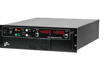
Silicon Carbide (SiC): Exhibits superior thermal conductivity, higher breakdown voltage capabilities (1200V to 3300V+), and higher thermal tolerance. SiC MOSFETs excel in high-power, high-voltage industrial SMPS applications above 3kW to 150kW+, such as green hydrogen electrolyser front-ends, high voltage DC supplies, EV fast chargers, and heavy industrial transformer rectifiers.
Q4: How does thermal derating affect the sizing and MTBF of an industrial SMPS in closed-chassis enclosures?
Answer: Thermal stress is the single primary driver of semiconductor degradation and electrolytic capacitor dry-out in power supplies. According to the Arrhenius law, every 10°C rise in capacitor operating temperature reduces its operational lifetime (MTBF) by 50%.
When selecting an SMPS for closed-chassis or high-ambient industrial environments (>40°C or >50°C), design engineers must consult the manufacturer's thermal derating curve. Typically, an SMPS rated for 1000W output at 50°C forced-air cooling may derate linearly by 2.5% per °C up to 70°C, providing only 500W of usable continuous power at 70°C unless supplementary baseplate conduction cooling or liquid cooling cold plates are implemented.
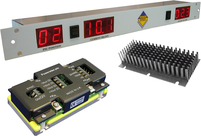
To maximize MTBF (e.g., >500,000 hours under Telcordia or MIL-HDBK-217F standards), engineers should oversize the SMPS power envelope by 20%–30% above maximum steady-state system load or utilize baseplate-cooled modular SMPS architectures like the Powerstax TVS series.
Q5: What safety isolation and leakage current standards are required when specifying an SMPS for medical equipment versus industrial systems?
Answer: Safety isolation requirements differ fundamentally between industrial and medical sectors:
Industrial SMPS Standards (EN/IEC 62368-1): Requires standard safety isolation between input AC lines and low-voltage output rails (typically 1.5kVAC to 3kVAC isolation). Earth leakage current limits are generally set at 3.5mA, focused primarily on operator protection and equipment fire safety.
Medical SMPS Standards (IEC/EN 60601-1 3rd/4th Edition): Requires Means of Patient Protection (MOPP) and Means of Operator Protection (MOOP). A 2xMOPP rating requires 4000 VAC isolation, 8mm creepage distance, and 5mm clearance. Furthermore, earth leakage currents must remain extremely low (<300µA for standard medical devices, and <100µA or <10µA touch current for patient-connected BF/CF body-floating applications) to prevent micro-shock risks. The Powerstax Medistax® platform is engineered specifically to meet these stringent 2xMOPP criteria.
Q6: Why should OEMs consider a modified-standard or value-added SMPS over fully bespoke custom development?
Answer: Ground-up custom SMPS design entails high Non-Recurring Engineering (NRE) costs, extensive engineering risk, and lengthy international safety/EMC certification cycles lasting 12 to 18 months. Conversely, catalog off-the-shelf power supplies often fail to meet exact mechanical dimensions, thermal mounting constraints, or specific output voltage combinations.
A modified-standard SMPS approach bridges this gap by modifying proven, pre-certified power building blocks (such as the Powerstax A Series or TVS series). Engineers can rapidly customize output wiring looms, mechanical mounting brackets, digital firmware settings, conformal coatings, or thermal baseplates. This strategy cuts NRE expenses by up to 70%, lowers unit cost, and reduces time-to-market from years to a matter of weeks while maintaining ISO 9001 quality assurance.