UK / Europe: +44 1268 568200 USA / Canada: +1 877 215 8463
in
0%

MIL-COTS DC-DC Converters combine commercial availability with performance requirements common in military and aerospace electronics. They convert one direct-current voltage into another, helping equipment operate reliably from batteries, vehicle power systems, or unstable supply rails. A typical unit may accept a 28-volt input and provide regulated 5-volt, 12-volt, or multiple outputs. Inside, switching transistors rapidly control energy through magnetic components, while feedback circuits maintain the required output voltage.

Built for demanding environments, these converters often include electrical isolation, overvoltage protection, short-circuit protection, and filtering against electromagnetic interference. Their metal cases can improve shielding and heat transfer. Engineers may also examine vibration tolerance, temperature range, humidity resistance, and connector reliability before selecting a model. Details matter. A converter can function perfectly on a laboratory bench yet fail when exposed to engine noise, rapid temperature changes, or restricted airflow.

The term “MIL-COTS” does not automatically guarantee compliance with every military standard. Certification, testing records, and the manufacturer’s quality controls must be checked carefully. That distinction is sometimes overlooked. Reliable evaluation includes reviewing efficiency curves, transient response, derating guidance, and thermal measurements under realistic loads. Experienced designers also allow margin rather than operating continuously at the published limit. This article explains how MIL-COTS DC-DC Converters work, where they fit in rugged power architectures, and which practical specifications deserve closer attention. Some applications need customized qualification, and a catalog part may not be sufficient. That uncertainty is worth acknowledging before deployment.
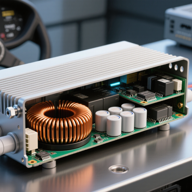
What Are MIL-COTS DC-DC Converters and How Do They Work?

Definition and Purpose of MIL-COTS DC-DC Converters

MIL-COTS DC-DC converters are commercially available power modules adapted for military and aerospace applications. Their purpose is simple: convert one direct-current voltage into another, stable voltage. A vehicle battery might provide 24 volts, while a sensor needs 5 volts. The converter manages that difference. It can also provide electrical isolation, filtering, current limiting, and protection against voltage spikes. These features help sensitive equipment operate near radios, motors, and changing power sources.

In practical designs, engineers select a converter by checking input range, output current, efficiency, temperature rating, vibration resistance, and fault behavior. A sealed module may sit inside a vehicle enclosure, where heat builds quickly and airflow remains limited. MIL-COTS products can reduce development time because they use established commercial production methods. However, “military” does not automatically mean suitable for every mission. Qualification levels, testing records, and system requirements still need careful review. That detail is easy to overlook.

Tips: Confirm the real input range, not just the nominal voltage. Check startup behavior with the intended load. Review derating data at high temperature. Allow space for cooling. If isolation is required, verify the isolation rating and test method. One mistake remains common: choosing by wattage alone. Transient response, connector layout, and electromagnetic noise can matter just as much. Good documentation supports reliable decisions, but field measurements should challenge assumptions when conditions differ.

Key Components and Internal Power-Conversion Process

MIL-COTS DC-DC converters adapt electrical power for demanding military and aerospace equipment. “COTS” means commercial off-the-shelf, while “MIL” indicates added screening, testing, and ruggedization. They are not automatically fully qualified military hardware. That distinction matters.

Inside, an input filter suppresses conducted noise and protects the source. A switching controller rapidly drives power MOSFETs. The switches send pulses through an inductor or transformer, storing and transferring energy at high frequency. A rectifier and output capacitor then smooth the waveform. A feedback loop measures output voltage and adjusts the duty cycle within microseconds. Protection circuits monitor overvoltage, overcurrent, short circuits, and excessive temperature. The converter may shut down before a small fault becomes a system failure.

The details are physical. A transformer may sit beside heat-spreading metalwork, while airflow removes heat from the switching stage. Galvanic isolation can separate a noisy input bus from sensitive sensors. According to MarketsandMarkets’ 2024 Military Power Supply Market report, demand is supported by wider electrification and modernized defense platforms. The report projects continued market growth through the decade, although estimates vary by scope and region. That uncertainty deserves attention. A converter can meet a headline efficiency target yet fail inside a cramped enclosure. Thermal testing, conducted-emissions measurements, vibration checks, and load-transient testing reveal the practical weaknesses. In real integration, the first design pass is rarely perfect. Real hardware teaches more.

How MIL-COTS Converters Regulate and Deliver Output Power

MIL-COTS DC-DC converters adapt commercial switching technology for demanding military environments. They commonly accept a 28 VDC or 270 VDC bus and provide tightly controlled outputs for processors, sensors, and communication equipment. A switching transistor chops the input rapidly. A transformer or inductor then transfers energy at a higher frequency. Rectifiers and capacitors smooth that energy into usable DC power.

Output regulation depends on feedback. A voltage sensor compares the output with a reference value. The controller adjusts pulse-width modulation when the load changes. If a radar module suddenly starts transmitting, the converter increases energy delivery within microseconds. Protection circuits limit overcurrent, overvoltage, overheating, and short-circuit damage. Industry test data often reports 85% to 95% efficiency for modern isolated converters. A 2024 military power-supply market assessment also identified efficiency, thermal density, and electromagnetic compatibility as leading design priorities. Those figures vary by topology and temperature.

Tips: Check transient-response curves, not only rated wattage. Confirm the input range, isolation rating, cooling method, and conducted-emissions performance. MIL-STD-704 power variations and MIL-STD-461 electromagnetic tests can expose weaknesses early. In field evaluations, wiring impedance often changes the result. That detail is easy to miss. Engineers may also overestimate efficiency because laboratory airflow is better than installed airflow. A converter that delivers 200 W on a bench may deliver less inside a sealed enclosure. Leave thermal margin. Recheck it after vibration and temperature testing.

Military Standards, Environmental Ratings, and Reliability Features

MIL-COTS DC-DC converters are commercial power modules designed to meet selected military requirements. They accept an uneven DC input and switch it at high frequency. Magnetic components then transfer energy to a regulated output. Feedback circuits adjust switching as the load changes. Isolation may separate sensitive electronics from noisy vehicle power.

Military standards focus on more than voltage conversion. Qualification can include vibration, mechanical shock, humidity, temperature cycling, altitude, and electromagnetic interference. Environmental ratings should match the installation. A converter inside an unsealed ground vehicle faces dust, condensation, and sudden temperature changes. Reliability features often include input filtering, overvoltage protection, current limiting, thermal shutdown, and controlled startup. Derating the converter also reduces stress on capacitors and switching devices. However, a military test does not guarantee every field outcome. Test conditions may not reflect years of maintenance errors or poor airflow. MTBF figures are useful, but they should not replace evidence from inspection and application testing.

Tips: Check the exact qualification report, not only the standard number. Confirm input transients, isolation voltage, cooling method, and connector strength. Leave thermal margin. A small enclosure can become surprisingly hot. Also review manufacturing controls, screening records, and failure analysis procedures. These details are less impressive than a rugged label, yet they often decide whether the power system remains stable.

What Are MIL-COTS DC-DC Converters and How Do They Work? - Military Standards, Environmental Ratings, and Reliability Features
Data Dimension Technical Description Typical MIL-COTS Characteristics
Definition MIL-COTS DC-DC converters are commercially manufactured power-conversion modules designed for military and aerospace equipment. They combine commercial production methods with military-oriented electrical, mechanical, environmental, and quality requirements. Military application suitability depends on the exact converter, qualification level, screening process, and system requirements. “MIL-COTS” is not, by itself, a single universal certification.
Basic Function The converter receives unregulated or regulated DC power, switches it at high frequency, transfers energy through an inductor or transformer, rectifies and filters the output, and uses feedback control to maintain the required voltage. Common functions include step-down, step-up, inverting, isolation, and multiple-output DC conversion.
Electrical Isolation Isolated designs use a high-frequency transformer to separate the input and output circuits. Non-isolated designs share a common electrical reference and are generally smaller and simpler. Isolation is selected according to safety, grounding, fault-containment, noise, and system architecture requirements. The required isolation voltage must be verified from the product test data.
Input Voltage Range Military vehicles, aircraft, ships, and field systems can experience input variation, transients, interruption, and electrical noise. A qualified converter must be matched to the platform power bus rather than only to its nominal voltage. Typical military input buses may include 12 V, 24 V, 28 V, 48 V, 270 V, or other application-specific levels. Input range and transient limits vary by design.
Output Regulation Feedback circuitry compares the output with a reference and adjusts the switching duty cycle or operating frequency to compensate for input and load changes. Important specifications include line regulation, load regulation, output ripple, transient response, remote sense, and startup behavior.
Efficiency and Thermal Design Switching conversion normally provides higher efficiency and lower heat generation than linear regulation. However, switching losses, magnetic losses, conduction losses, and semiconductor temperature still require careful thermal design. Efficiency is load-, input-, switching-frequency-, and temperature-dependent. Conduction cooling, baseplate cooling, airflow, or a combination may be used.
MIL-STD-810 Environmental Testing MIL-STD-810 provides laboratory test methods for environmental stresses such as temperature, altitude, humidity, vibration, shock, sand and dust, salt fog, and other conditions. The applicable methods and procedures must be identified for the intended platform. Compliance is configuration- and test-method-specific. A statement that a product is “810 tested” should be supported by the applicable methods, procedures, severity levels, and test report.
MIL-STD-461 EMC and EMI MIL-STD-461 defines electromagnetic interference and susceptibility requirements for equipment and subsystems. Tests may address conducted emissions, radiated emissions, conducted susceptibility, and radiated susceptibility. Typical requirements can include input-port conducted emissions and susceptibility, output-port emissions, and radiated emissions or susceptibility. The exact test set depends on the equipment installation.
MIL-STD-704 Aircraft Power MIL-STD-704 defines characteristics of aircraft electric power at the equipment interface, including normal and abnormal voltage, frequency, transient, and power-quality conditions for applicable aircraft power systems. A converter intended for aircraft use must be evaluated against the specific revision and aircraft power type, such as 28 VDC or 270 VDC systems.
MIL-STD-1275 Ground-Vehicle Power MIL-STD-1275 addresses electrical characteristics and power-quality conditions associated with 28 VDC ground-vehicle electrical systems, including voltage variation, transients, ripple, and conducted disturbances. The applicable revision and the vehicle electrical architecture should be confirmed before selecting an input protection and filtering design.
Input Protection Protection circuits may include reverse-polarity protection, input fuses, current limiting, surge suppression, transient-voltage suppressors, active inrush limiting, and undervoltage or overvoltage lockout. Protection improves survivability during abnormal bus conditions, but it does not automatically establish compliance with a particular military power standard.
Output Protection Common features include short-circuit protection, overcurrent limiting, overvoltage protection, thermal shutdown, soft start, and controlled restart after a fault. Protection behavior may be hiccup, latch-off, constant-current, or foldback. The recovery method should be compatible with the powered load.
Operating Temperature Military-grade converters are designed for operation over a broader temperature range than ordinary commercial modules, with performance limited by semiconductor, magnetic, capacitor, insulation, and mechanical constraints. Common qualified ranges include approximately −55°C to +85°C case temperature, with some designs supporting higher case or junction temperatures. The specified temperature must not be confused with ambient temperature.
Altitude and Low Pressure Reduced air pressure lowers convective cooling and can increase electrical-clearance and arcing concerns. Altitude testing evaluates operation, insulation, cooling, and dielectric behavior under low-pressure conditions. The allowable altitude and derating depend on construction, insulation system, cooling method, and the applicable environmental test procedure.
Vibration and Mechanical Shock Ruggedized construction may use reinforced circuit boards, secured magnetic components, locking hardware, conformal coating, and mechanical mounting designed to reduce fatigue and resonance-related failures. Qualification levels vary by vehicle, installation location, vibration spectrum, shock pulse, mounting method, and test profile.
Humidity, Salt Fog, and Contamination Moisture and contamination can reduce insulation resistance, promote corrosion, and increase leakage or tracking. Enclosures, conformal coatings, corrosion-resistant finishes, and controlled materials may be used to reduce these risks. Environmental resistance depends on enclosure design, coating coverage, connector selection, sealing, and the specific test exposure.
Thermal Management Heat is commonly transferred from power components to a case, baseplate, chassis, or heat sink. Installation thermal resistance is part of the converter’s real operating condition. Output power usually requires derating as case or ambient temperature rises. The system designer should use the manufacturer’s thermal curves and mounting recommendations.
Reliability Prediction Reliability analysis may use component failure-rate data, stress analysis, temperature profiles, derating, and mission conditions. MIL-HDBK-217 is a historical reliability-prediction reference often cited in military programs, but it is not a guarantee of field life. Reported values may include MTBF or predicted failure rate. These figures are meaningful only when the prediction method, environment, temperature, duty cycle, and confidence assumptions are stated.
Component Derating Derating limits electrical, thermal, voltage, current, and power stress below the component’s maximum ratings. It can improve reliability by reducing overstress and aging mechanisms. Commonly reviewed parts include electrolytic capacitors, ceramic capacitors, semiconductors, magnetic components, resistors, connectors, and insulation systems.
Screening and Qualification Screening may include visual inspection, burn-in, temperature cycling, vibration, electrical testing, and other controls intended to identify workmanship or early-life defects. Qualification demonstrates performance against a defined test plan. Screening is not the same as qualification, and neither replaces system-level verification in the final equipment installation.
EMI Filter Integration Input and output filters, shielding, controlled switching edges, transformer design, grounding, and PCB layout help limit conducted and radiated electromagnetic noise. Converter compliance can change when cable length, grounding, enclosure, load impedance, and neighboring equipment change; final integration testing is therefore important.
Mechanical Construction Rugged converters may use sealed or semi-sealed housings, metal cases, threaded mounting points, board stiffeners, conformal coating, and fixed or derated connectors. Mechanical design should match the available mounting surface, cooling path, connector system, sealing requirement, and shock and vibration environment.
Maintainability and Documentation Military programs typically require traceability, configuration control, inspection records, test evidence, interface definitions, derating information, and clear installation guidance. Useful documentation includes datasheets, qualification reports, test conditions, reliability assumptions, pin assignments, thermal curves, and revision history.
Selection Checklist Selection should consider nominal and transient input voltage, output voltage and current, isolation, efficiency, operating temperature, cooling method, EMI limits, vibration and shock, altitude, protection behavior, mechanical interfaces, and documentation. The correct device is the one whose verified ratings and test evidence match the complete mission profile—not simply one described as military-grade.

Common Applications and Selection Considerations

MIL-COTS DC-DC converters are rugged power modules designed for demanding environments. They convert an unstable DC input into a controlled output voltage. The term MIL-COTS usually indicates commercial hardware adapted for military-style durability, testing, and documentation.

Common applications include aircraft electronics, ground vehicles, radar subsystems, communication equipment, and industrial control cabinets. They also serve remote sensors where maintenance access is limited. In a vehicle, a converter may reduce a 28 VDC bus to 5 VDC for processors and sensors. Isolation can prevent noisy power paths from disturbing sensitive circuits. It matters more than many designs expect.

Selection should begin with the real input range, not its nominal value. A 28 VDC system may experience starts, surges, and wiring drops. Check output current, peak load behavior, efficiency, switching frequency, and isolation rating. Thermal performance is equally important. A module rated for 200 W in open air may deliver much less inside a sealed enclosure. Measure the case temperature under actual airflow conditions.

EMI performance needs careful review. Filters, grounding, shielding, and cable layout can change results significantly. In bench testing, a converter may appear quiet until a long harness is connected. That detail is easy to miss. Verify transient response, protection features, vibration resistance, and derating guidance before approval. Certification documents help, but they do not replace system-level testing. Some specifications still leave practical questions unanswered.

FAQS

What does MIL-COTS mean in a DC-DC converter?

It combines commercial technology with added screening, testing, and ruggedization. It is not automatically fully qualified military hardware.

How does a MIL-COTS converter change input power?

An input filter reduces conducted noise. Switching transistors chop the input into high-frequency pulses. An inductor or transformer transfers the energy.

How is the output voltage regulated?

A voltage sensor compares output voltage with a reference. A feedback controller changes the switching duty cycle within microseconds.

What happens when the load changes suddenly?

The converter increases or reduces energy delivery quickly. For example, a transmitting radar module can create a sharp load increase.

Which protection features are commonly included?

Protection circuits monitor overvoltage, overcurrent, short circuits, and excessive temperature. The converter may shut down before damage spreads.

Why are thermal tests important?

A converter may perform well on a ventilated bench but fail inside a sealed enclosure. Heat-spreading metalwork and airflow strongly affect performance.

What efficiency can modern isolated converters achieve?

Reported efficiency commonly ranges from 85% to 95%. Results vary with topology, temperature, load, and cooling conditions.

What should engineers check beyond rated wattage?

Check transient-response curves, input range, isolation, cooling, and conducted emissions. A 200-watt rating alone proves very little.

Why can field performance differ from laboratory results?

Wiring impedance, vibration, temperature, and restricted airflow can change the result. The first design estimate is often wrong.A converter may pass bench testing yet struggle after installation. Recheck thermal margin.

Conclusion

MIL-COTS DC-DC Converters are rugged power-conversion devices designed to provide stable, efficient, and reliable DC voltage for military and other demanding applications. They convert an unregulated DC input into a controlled output by using components such as switching transistors, transformers or inductors, rectifiers, capacitors, feedback circuits, and control logic. Through high-frequency switching and continuous feedback, these converters adjust their operation to maintain the required output voltage despite changes in input power, load demand, or operating conditions.

Built for challenging environments, MIL-COTS DC-DC Converters typically emphasize compliance with military performance standards, wide temperature tolerance, resistance to vibration and shock, electromagnetic compatibility, and long-term reliability. They are commonly used in communication systems, avionics, vehicles, radar equipment, industrial controls, and portable electronic platforms. When selecting a converter, engineers should consider input and output voltage ranges, power rating, efficiency, isolation, thermal management, environmental requirements, physical size, protection features, and system integration needs.


Ethan

Ethan

Ethan is a professional marketing specialist with a strong understanding of market trends, customer needs, and product value. As a key member of the company’s marketing team, he is responsible for communicating the practical benefits of our solutions and helping customers make informed decisions.......