Explore our flagship OEM rectifier diodes, silicon controlled rectifiers (SCR), high-voltage silicon stacks, and custom-engineered power conversion sub-assemblies.
In modern electrochemistry, advanced surface finishing, green hydrogen generation, and high-frequency induction processing, conventional direct current (DC) power delivery reaches strict physical limitations. Standard continuous DC rectifiers often induce concentration polarization, excessive boundary thermal gradients, and sub-optimal ion deposition rates. As a premier Custom OEM Pulse Rectifier Factory & Exporter, our engineering division manufactures tailored pulsed power systems—including forward pulse, unipolar high-frequency pulse, and reverse periodic pulse thyristor topologies—engineered to overcome mass-transport bottlenecks and dramatically enhance process dynamics.
Pulse rectification operates by modulating power delivery into rapid microsecond or millisecond bursts defined by peak current density ($I_{\text{peak}}$), pulse duration ($T_{\text{on}}$), relaxation time ($T_{\text{off}}$), and reverse pulse amplitude ($I_{\text{rev}}$). By modulating duty cycles ($Duty = T_{\text{on}} / (T_{\text{on}} + T_{\text{off}})$), engineers can dictate grain boundary nucleation, control oxide layer thickness, and maintain low thermal stress across delicate component matrices.
Unlike standard switched-mode power supplies (SMPS) that output steady DC ripple under 1%, custom pulse rectifiers actively manipulate the hydrodynamic diffusion layer ($\delta$). During the $T_{\text{on}}$ interval, metal ions are consumed rapidly at the cathode. During the $T_{\text{off}}$ period, ions replenish near the boundary, minimizing dendrite formation and eliminating micro-void formation in specialized electroplating, electrochlorination, and plasma electrolytic oxidation (PEO) applications.
| Performance Vector | Standard Continuous DC Rectifier | Advanced OEM Switched Pulse Rectifier | Bipolar Reverse-Pulse Thyristor System |
|---|---|---|---|
| Diffusion Layer Boundary ($\delta$) | Thick, stagnant polarization zone | Significantly reduced via pulse relaxation | Ultra-thin; periodic reverse dissolves micro-burrs |
| Peak Current Density Capability | Limited to continuous thermal max | 3x to 10x higher peak current spikes | Up to 15x peak current with reverse pulse energy |
| Thermal & Ohmic Stress | Constant heating; high cooling demand | Controlled thermal dissipation in $T_{\text{off}}$ phase | Lowest localized thermal buildup; precise control |
| Target Industrial Sectors | General Anodizing, Basic DC Drives | Precision Electroplating, RF Heating | Hydrogen Electrolysers, PCB Micro-vias, PEO |
Building upon over three decades of British power engineering legacy (tracing back through established high-power design traditions under the Powerstax umbrella), our custom OEM manufacturing lines integrate rigorous qualification standards across every assembly stage. We design and build AC-DC converters up to 10 kW per single chassis, DC-DC converter modules up to 7.2 kW, high-voltage DC power supplies reaching 150 kW / 200 kV, dynamic frequency converters up to 120 kVA, and megawatt-scale thyristor-controlled transformer rectifiers.
Full design compliance with MIL-STD-704, MIL-STD-1275, and MIL-STD-461. Built for extreme shock, vibration, and severe electromagnetic interference (EMI) environments.
We do not adapt off-the-shelf catalog units. Our thermal and electrical engineers configure magnetic core geometry, semiconductor switching topology, and liquid cooling channels to your precise load dynamics.
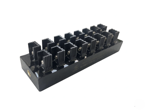
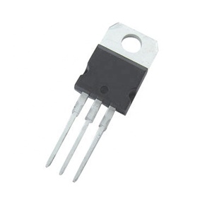
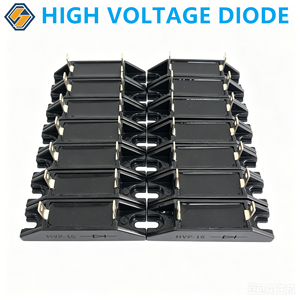
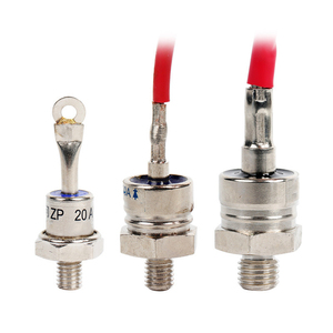
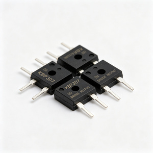
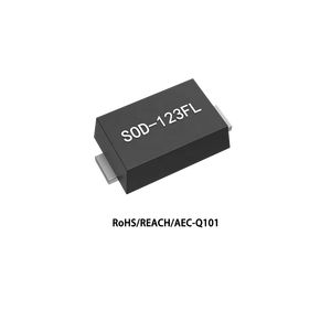
100% original semiconductor sourcing with lot-code traceability (including SOD-123FL, TO-220, ZP-series spiral rectifiers, and high-voltage silicon blocks) under certified ISO 9001 management.
The global industrial power supply and pulse rectifier landscape is undergoing a structural transition driven by decarbonization, green hydrogen electrolyser expansion, microelectronics miniaturization, and green surface engineering standards. B2B procurement managers and system engineering leads must adapt their sourcing strategies to capture key technical shifts:
Silicon Carbide (SiC) MOSFETs and Gallium Nitride (GaN) high-electron-mobility transistors are replacing legacy silicon rectifiers in high-frequency pulse power supplies. SiC-based pulse rectifiers allow switching frequencies exceeding 100 kHz with thermal losses cut by over 40%. This enables compact, high-power-density enclosures for space-constrained semiconductor tools and deployable military platforms.
Proton Exchange Membrane (PEM) and Alkaline electrolyser plants are moving toward micro-pulsed current regimes to mitigate catalyst degradation and improve stack efficiency ($kWh/kg\,H_2$). Large-scale OEM purchasers now demand thyristor-controlled transformer rectifiers with active dynamic harmonic mitigation, high power factors ($>0.95$), and integrated Modbus TCP or EtherCAT communication.
As pulse peak currents scale into thousands of amperes ($A$), air-cooled heat sinks reach volumetric limits. Modern OEM procurement mandates direct water-glycol cooled cold plates, sealed IP65 or IP67 enclosures, and internal thermal sensor arrays to prevent corrosion in electrochlorination skids, offshore oil platforms, and chemical electroplating lines.
Sourcing a custom pulse rectifier requires rigorous evaluation of electrical parameters, duty cycle limits, and thermal tolerances. Below is the decision framework utilized by Senior Power Conversion Engineers when defining custom OEM specifications:
We provide clean-sheet or modified-standard customization covering peak output voltage (up to 200 kV), peak current (up to several kA), pulse frequency range (1 Hz to 200 kHz), pulse duty cycles (0.1% to 99.9%), reverse pulse ratio, cooling method (forced air, convection, or liquid-cooled), enclosure IP rating, and digital communications (CANbus, RS485, EtherCAT).
Pulse rectifiers deliver high instantaneous peak currents that accelerate crystal nucleation on substrate surfaces. During the pulse-off time, metal ion depletion at the cathode is replenished, preventing dendrite growth, reducing grain size, and producing denser, harder, and less porous metallic coatings.
All custom OEM designs undergo structured compliance routes including IEC/EN 61010 for electrical safety, IEC 60601 for medical platforms, ISO 9001 for quality control, RoHS/WEEE for environmental safety, and MIL-STD-704/1275/461 for defense deployments.
Initial engineering concept reviews and thermal/EMC simulations are typically completed within 1–2 weeks. Functional prototypes are delivered in 6–10 weeks depending on custom magnetics fabrication and compliance testing requirements, followed by volume manufacture under strict ISO 9001 controls.
Submit your custom electrical specifications, target load parameters, thermal profile, and compliance goals directly to our engineering division. We will evaluate your requirements and provide a tailored technical proposal.