Engineered for extreme environmental resilience, low leakage inductance, high dielectric isolation, and precision pulse signal shaping.
In high-frequency power electronics, pulsed energy conversion, and industrial signal processing, the pulse transformer serves as an indispensable galvanic bridge. Designed specifically to transmit rectangular electrical pulses with ultra-fast rise times and minimal amplitude distortion, modern pulse transformers must maintain rigorous electrical isolation while handling high peak currents and voltages. As power conversion topologies migrate toward Wide Bandgap (WBG) semiconductors—such as Silicon Carbide (SiC) MOSFETs and Gallium Nitride (GaN) High Electron Mobility Transistors (HEMTs)—the demand on pulse transformer manufacturers to minimize leakage inductance, interwinding capacitance, and core saturation has increased exponentially.
As a globally recognised OEM/ODM pulse transformer factory and custom magnetic solutions provider, our engineering methodology relies on first-principles electromagnetic modeling, advanced toroidal and planar core geometries, and proprietary winding topologies. Whether deployed in radar pulse-forming networks, gate-drive isolation for high-power thyristor switchgear, electrochlorination power supplies, or particle acceleration RF modulators, our custom magnetic components guarantee unyielding transient performance, strict compliance with IEC/EN standards, and enhanced operational integrity in non-stop industrial installations.
Core Technical Advantage: Optimized Volt-Second Product ($E \cdot t$) design ensures zero core saturation during maximum pulse-width transients, while interwinding Faraday shielding suppresses common-mode $dv/dt$ noise above 100 V/ns in next-generation SiC/GaN gate drive circuits.
A pulse transformer differs fundamentally from standard continuous-wave (CW) AC power transformers. Rather than operating at a static sinusoidal frequency (e.g., 50Hz or 60Hz), a pulse transformer operates under transient rectangular voltage excitation, requiring precise control over transient magnetizing current and energy storage. The performance of a pulse transformer is primarily dictated by its Volt-Second Product ($E \cdot t$), magnetic flux density swing ($\Delta B$), leakage inductance ($L_l$), and distributed capacitance ($C_w$).
Gate drive transformers provide galvanic isolation between low-voltage control microcontrollers (DSP/FPGA) and high-voltage power switches (IGBTs, Thyristors, SiC MOSFETs). Key engineering parameters include minimal propagation delay ($\tau_d < 20\,\text{ns}$), negligible rise time degradation, and partial discharge immunity exceeding 5 kV RMS continuous working isolation. Distributed interwinding capacitance must be strictly minimized to prevent false turn-on triggered by rapid $dv/dt$ transients across the power stage.
In pulsed laser systems, discharge igniters, radar transmitters, and medical X-ray generators, pulse transformers step up low-voltage capacitor discharges to tens or hundreds of kilovolts. These units require multi-stage oil or solid-epoxy encapsulation, custom segmented bobbins to control dielectric stress gradients, and high saturation flux density ($B_s$) nanocrystalline or amorphous ribbon cores to maximize power density while containing thermal losses.
Used extensively in telecommunications, digital interface protection, and medical equipment compliant with IEC 60601-1 2xMOPP (Means of Patient Protection). These micro-miniature pulse transformers feature tight magnetic coupling ($k > 0.999$) to deliver clean bitstreams without ringing or pulse tail droop, even under severe electromagnetic interference (EMI) background conditions.
From custom magnetics simulation to automated volume winding, we deliver complete lifecycle assurance for high-reliability applications.
We process ultra-high permeability ferrite, MnZn, Fe-based nanocrystalline, and NiFe tape-wound cores to optimize the B-H loop specifically for your operating frequency, duty cycle, and thermal environment.
Utilizing bifilar/trifilar, sector, and interleaved winding architectures to achieve leakage inductances below 0.1% of total primary inductance, drastically cutting voltage spikes and snubber dissipation.
Every batch undergoes automated 100% screening for turn ratio, inductance, leakage inductance, interwinding capacitance, DC resistance, Hi-Pot isolation (up to 20kV), and partial discharge ($Q < 10\,\text{pC}$).
The table below provides engineering selection parameters comparing standard magnetic materials and power rectifier building blocks utilized across our pulse transformer and thyristor rectifier production lines:
| Core Material / Component | Saturation Flux Density ($B_s$) | Permeability ($\mu_r$) | Operating Freq. Range | Primary Application | Isolation Voltage (RMS) |
|---|---|---|---|---|---|
| MnZn High Permeability Ferrite | 0.45 - 0.52 T | 5,000 - 15,000 | 10 kHz - 2 MHz | Gate Drive & Signal Pulse Transformers | 3.75 kV to 6.0 kV |
| Nanocrystalline Ribbon (Fe-Based) | 1.20 - 1.35 T | 20,000 - 80,000 | 1 kHz - 100 kHz | High Energy Pulse / Power Conversion | 10 kV to 50 kV |
| Amorphous Metal Tape Core | 1.50 - 1.56 T | 1,000 - 10,000 | 500 Hz - 20 kHz | Pulsed Power Modulators & Radar | Up to 100 kV Oil Immersed |
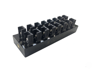
| 2CLG20KV High Voltage Block | N/A (Diode Block) | N/A | DC - 50 kHz Pulse | HV Cockcroft-Walton Multipliers & RF | 20 kV Direct Rating |
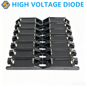
| HVP-16 HV Silicon Stack | N/A (Silicon Stack) | N/A | Fast Recovery Rectification | Industrial RF Heating & Induction | 17.5 kV Repetitive Peak |
The rapid advancement of decarbonization technologies, green hydrogen electrolysis, electric transport propulsion, and defense radar platforms is forcing a revolution in magnetics design. As power densities scale beyond $100\,\text{W/in}^3$, pulse transformer suppliers are pivoting toward several groundbreaking technological shifts:
Silicon Carbide and Gallium Nitride devices switch up to 20 times faster than silicon IGBTs, creating extreme voltage transients ($dv/dt > 150\,\text{V/ns}$). Pulse transformers must evolve to prevent capacitive surge current injection into gate controllers. Advanced shielding techniques, such as dual-layer copper foil shield wraps combined with ultra-low dielectric constant ($\varepsilon_r < 2.2$) fluoropolymer insulation, are becoming standard specs for next-generation gate drive magnetics.
Conventional wire-wound bobbin structures are being superseded by multi-layer Printed Circuit Board (PCB) planar geometries and integrated matrix cores. Planar pulse transformers offer precise geometric repeatability, zero automated assembly variance, exceptional heat dissipation through direct copper clad plating, and profile heights as low as 4.5 mm. This architecture is vital for aerospace MIL-COTS converters and space-constrained server power modules.
Fe-based nanocrystalline materials are replacing silicon steel and standard nickel alloys in heavy industrial pulse transformers. Offering high saturation flux density ($1.25\,\text{T}$) coupled with minimal coercivity, nanocrystalline cores allow factory engineers to reduce transformer footprint by up to 40% while operating safely across ambient thermal ranges from $-55^\circ\text{C}$ to $+155^\circ\text{C}$.
The manual trial-and-error cycle of magnetic prototyping is being replaced by Finite Element Analysis (FEA) integrated with AI physics solvers. Our factory utilizes multi-physics simulation software to calculate 3D parasitic capacitance matrix elements, eddy current skin-depth losses, and local core hot-spots prior to tooling production, ensuring first-pass design qualification for complex OEM procurement projects.
Global procurement teams for industrial equipment, defense platforms, and power grids face heightened exposure to supply chain vulnerabilities, raw material price volatility, and evolving compliance mandates. Modern procurement strategies for magnetics and power semiconductors have shifted from pure unit-cost negotiation to long-term lifecycle value and risk resilience.
Procurement Insight: Leading OEM buyers are enforcing "Design for Traceability" requirements. Pulse transformer manufacturers must provide complete material lot origins—ranging from Enameled Copper Wire temperature ratings (Class H/N 180°C–200°C) toUL 94-V0 rated encapsulation resins.
Here are expert engineering answers to the most frequent technical and supply chain queries raised by hardware designers and global sourcing managers:
To deliver an exact technical proposal and quotation, our magnetics engineering team requires: (1) Primary Pulse Voltage & Duration ($E \cdot t$ product), (2) Operating Frequency and Duty Cycle, (3) Turns Ratio ($N_p : N_s$), (4) Required Primary Inductance and Maximum Allowed Leakage Inductance, (5) Dielectric Isolation Rating (RMS/Peak voltage and duration), (6) Operating Temperature Range, and (7) Physical Mounting Constraint (SMD, Through-Hole, or Chassis Mount).
Leakage inductance is minimized by maximizing the coupling coefficient between primary and secondary windings. We achieve this through: tight bifilar/interleaved winding techniques, utilizing toroidal or low-profile planar cores, keeping winding width wide while minimizing insulation layer thickness, and optimizing winding geometry via FEA magnetic flux modeling without compromising required dielectric safety distances (creepage and clearance).
While all gate drive transformers are technically pulse transformers, the term "pulse transformer" is a broader category encompassing high-power pulse shaping, voltage step-up, and signal isolation units. Gate drive transformers are specifically optimized for triggering power switches (IGBTs, Thyristors, MOSFETs), focusing on fast switching rise times, low interwinding capacitance to block $dv/dt$ noise injection, and precise volt-second balance to prevent core saturation during asymmetrical switching cycles.
Every single manufactured unit undergoes 100% automated screening for: Open-circuit Inductance ($L_o$), Leakage Inductance ($L_l$), DC Resistance (DCR), Turns Ratio & Polarity, Hi-Pot Dielectric Breakdown, and Insulation Resistance ($IR > 10^{10}\,\Omega$). For medical, military, or high-voltage lines, we also execute Partial Discharge testing ($Q < 10\,\text{pC}$ at specified working voltage) and thermal shock environmental cycling under ISO 9001 quality controls.
For standard catalog parts or pre-qualified modular platforms, prototype samples ship within 5 to 7 business days, with mass production lead times ranging between 3 to 5 weeks. For full-custom clean-sheet designs requiring custom bobbin tooling, prototype delivery is 2 to 3 weeks. We offer flexible MOQs starting at 50 pieces for specialized industrial/military builds up to high-volume automated production runs of 100,000+ units per month.
High temperatures reduce the saturation flux density ($B_s$) of ferrite cores, increasing the risk of core saturation if the transformer is operated near its limits. Furthermore, high temperature accelerates insulation degradation and increases copper DCR losses. Our factory selects high-curie-temperature ferrite grades ($T_c > 220^\circ\text{C}$) and Class H/N (180°C–200°C) wire/insulation to guarantee un-derated operation in elevated thermal environments.
Consult with our senior application engineers to review your custom pulse transformer specifications, power rectifier requirements, or high-voltage design challenges.
Get Catalog